Back to Top


Cable characteristic measurement

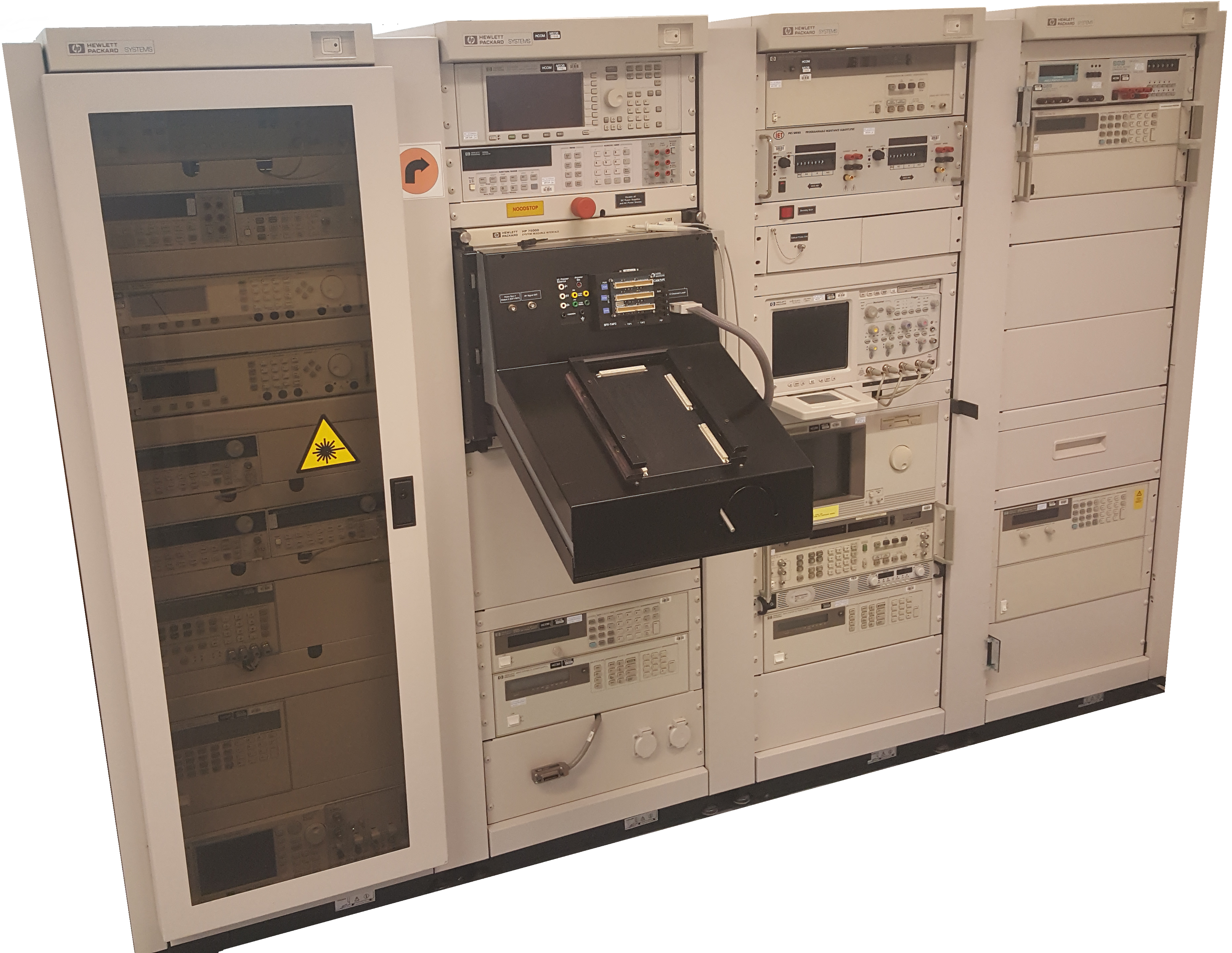
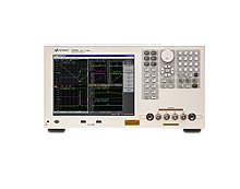
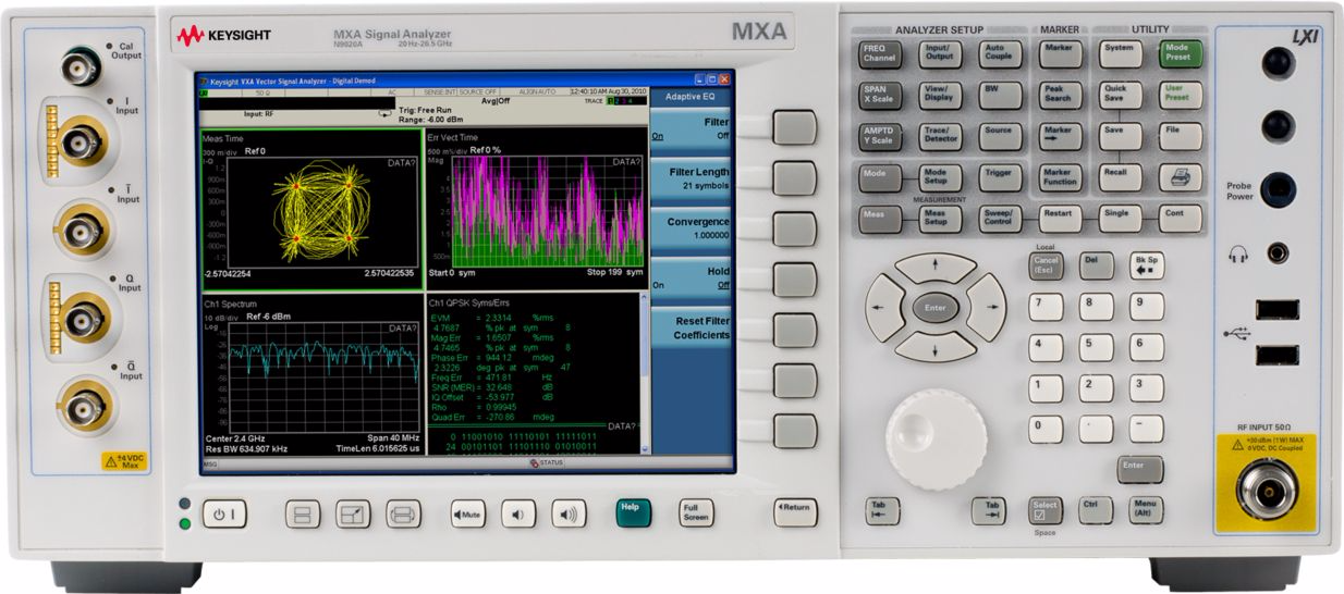
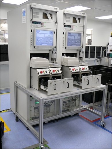
Cable characteristic measurement application using the E5061B-005 LF-RF Network Analyzer with option 005 for Impedance Analysis.


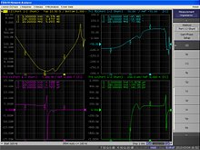
The network analyzer offers versatile network analysis in the broad frequency range from 5 Hz to 3 GHz. Comprehensive LF network measurement capabilities including built-in 1 Mohm inputs have been seamlessly integrated with the high-performance RF network analyzer. The analyzer has two kinds of test ports; the S-parameter test port (Port 1 and 2) and the gain-phase test port. The S-parameter test port has a 50 ohm built-in S-parameter test set that seamlessly covers a broad frequency range from 5 Hz to 3 GHz. The gain-phase test port has reference and test receiver inputs whose input impedance is switchable to 1 Mohm or 50 ohm. The frequency range is 5 Hz to 30 MHz. The most typical application is the frequency response analysis for low-frequency devices and circuits, such as OP amps and control loop circuits of DC-DC converters or in this case low-frequency cables.

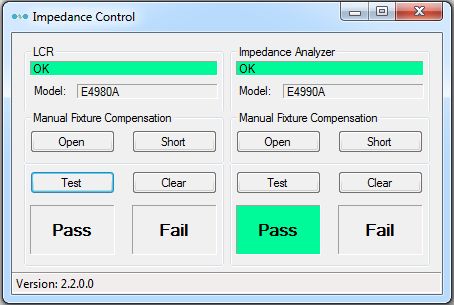
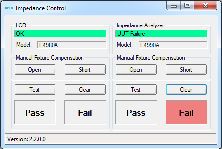
The cable characteristics measurements application helps the operator to conduct different kind of cable measurements (including calibration procedure).

Reflection method

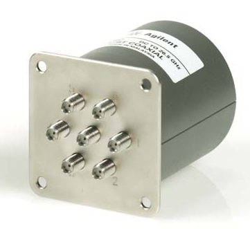
Using the S-parameter port-1 and port-2 50 ohm coaxial cables can be connected and measured via the binding post fixture. Other cable impedance measurements are conducted using an impedance transformer (BALUN). During calibration procedure the BALUN is included to measure and compensate for the BALUN frequency response. After calibration the reference pane is the BALUN.
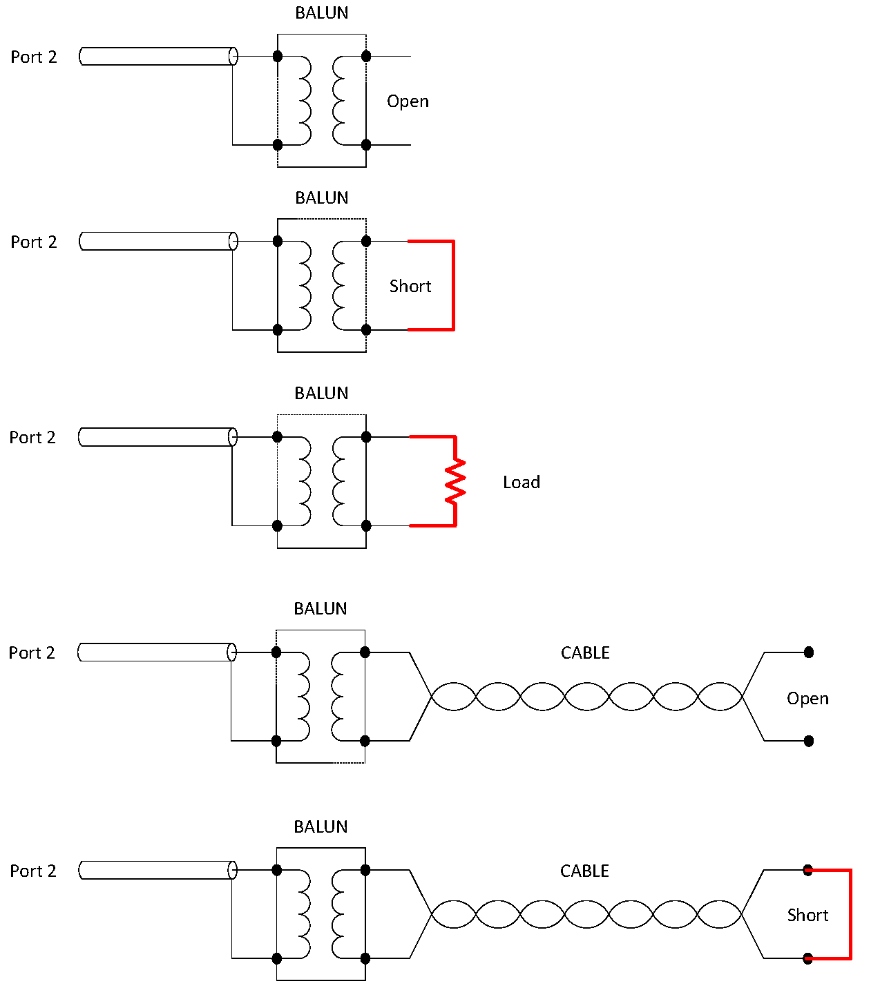
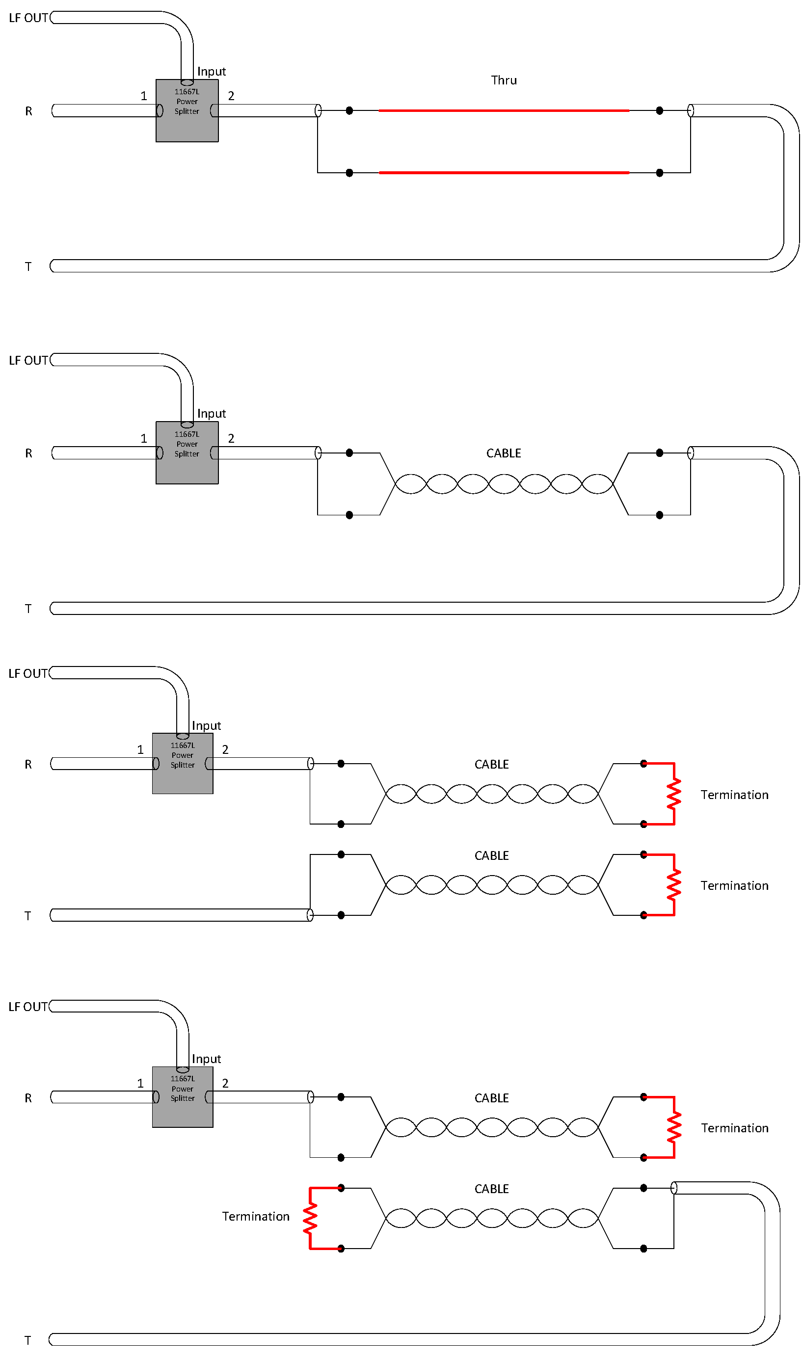
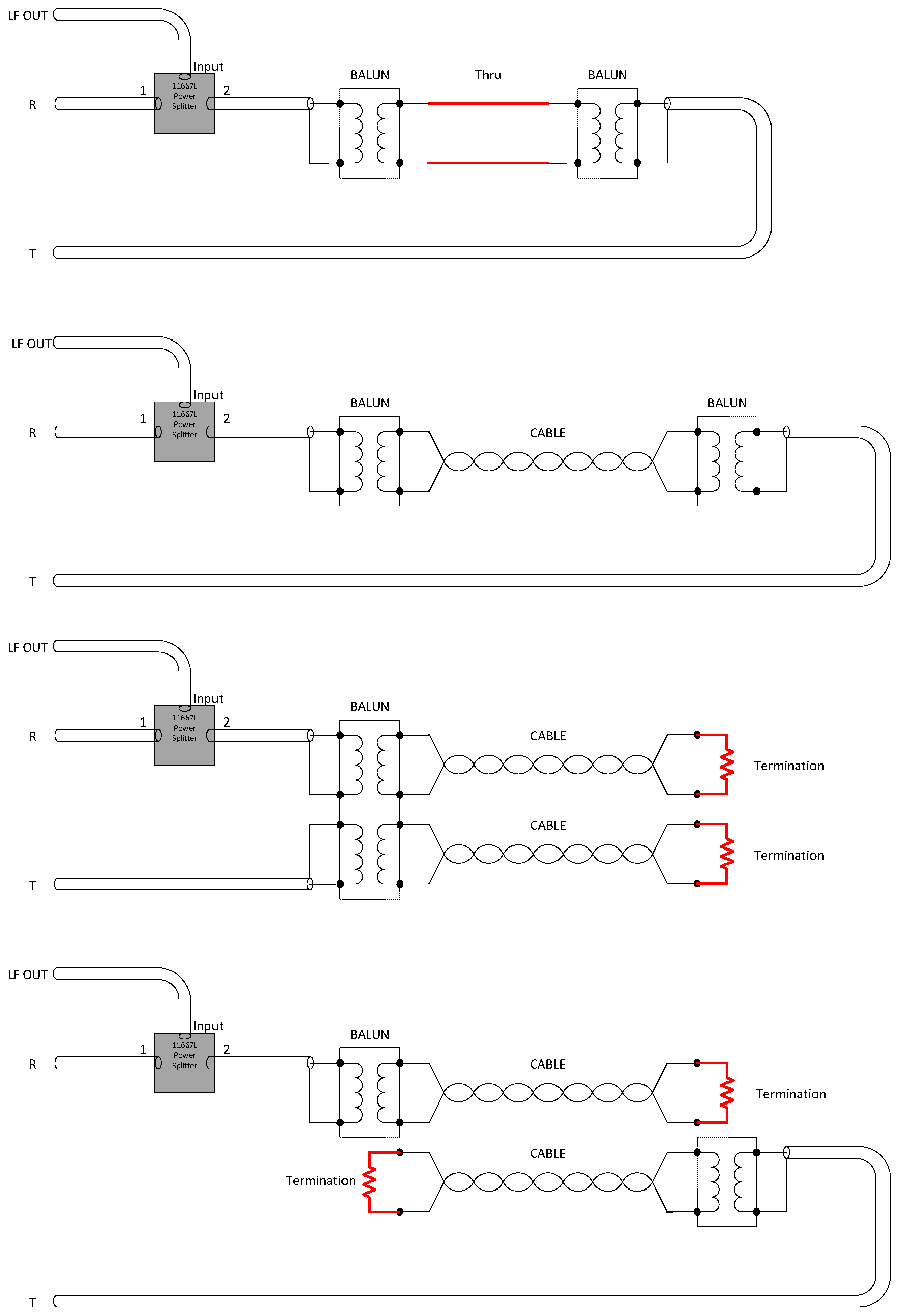
Series-thru method

Non-coaxial cables (twisted pair) are measured using the gain-phase test port. A power splitter is used to measure the reflected energy.
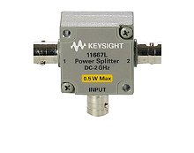
Below a few measurement types; Calibration-Thru, Cable-Thru, Cable-Far-End Cross-Talk and Cable-Near-end Cross-Talk.


Impedance measurement

Impedance measurement application using the E4980A LCR meter and E4990A Impedance Analyzer.


This application is used in a production line where electronic components are produced. At the end of the production line a robot is used to pick and place the components in a fixture. There is one fixture for LCR measurements and one fixture for the Impedance Analyzer. Limit Testing is done by the Application using Marker data from the Impedance Analyzer. There are 5 Markers used for this purpose. The setup of the Impedance Analyzer is stored in settings file on the instrument, the LCR setup is done by the Test Application using the parameters from the xml configuration file. The application is build using C# and Microsoft .NET framework 4.0. The application is communicating via LAN Sockets with the E4990A Impedance Analyzer and E4980A LCR meter.

The application communicates with the robot to perform complete measurement cycle for each component and to report if the component is Pass or Fail. The application is also logging all test results for later statistical analysis and performs the required calibration steps for both instruments.

For debugging purposes there are calibration and test buttons available to control the application without robot communication. These buttons are disabled during normal operation.

RF Switch-Box

RF Switch box solutions using the Keysight Technologies L4490A or L4491A frame.

This universal frame can be equipped with RF switch modules. The frame contains the hardware to control the switching via GPIB or LAN (LXI). The RF Switch box is used in combination with a RF-signal monitoring / alarm application using MXA signal analyzer. The application is remote controllable.


Functional Test Systems for automotive industry

Functional Test Systems are designed to test the product functionality. The goal is to guaranty the delivery of fully operational products to end users. The system presented here is one used for the Automotive industry. The system was build using “Keysight Technologies” components and included the testing of: RF, analog and digital signals combined with CAN-Bus communication paths. The tests and matrix switching are controlled by the “TestExecSL” test executive software platform. Other software modules are used to control the communication with: Databases, Bar/Data-Matrix scanner, Ticket printer and fixtures.

This automotive test system is used to test the functionality of the central control unit:

  • Air Back system
  • RF control of open/close doors, flashing lights depending on distance (RF-Level)
  • Cruise control
  • Radio control
  • Lights ...

RF shielded tray
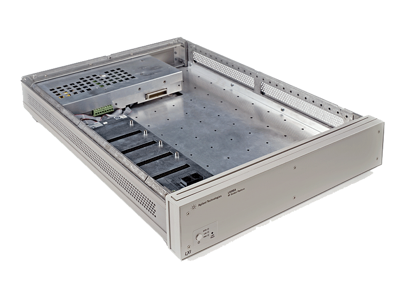
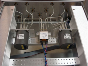
The RF part of the test required a RF shielded box (-70 dB)


Functional Test Systems for aerospace defence

Test automation software like "TestExecSL" (Keysight Technologies), "TestStand" (National Instruments) or "TAP" (Test Automation Platform of Keysight Technologies) is mainly used for building Functional Tests systems like the one below. These platforms are programming language independent. Handle switching components and include exception handing.